
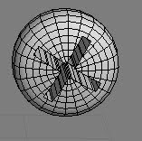
I repeat do this part a lot of times because I hope to find a suitable way to make this a part .By the end, I decided to use the Lathe process to make this part. First, I observed of photos, used the line to drawn the cross-section diagram of this part. Then add a modifier is the Lathe, modify the parameters, raise segments and press Mix button. Then it was converted to editable poly, select the vertex to adjust, remove the Cap, finally, and add a modifier is the Meshsmooth. Now, this section is complete. In the production of this part, there are some problems. When I draw the cross-section, I always do not know how to paint it. I repeated many times. Finally I got good results.

This part is similar with the previous part of the production, but it takes time to adjust vertex. In the production of this part, I import photos into 3D MAX. I use it as a reference map, in order to change the shape of component. First, create a Cylinder, converted to editable poly, select vertex. And then I adjust the point of Cylinder to similar with photos. Finally, I add a modifier is the Meshsmooth. Select the entire component, press shift button to copy. This section is complete.

This section is formed by the box and Cylinder. First, create a Cylinder, adjust the size. And then create six boxes, adjust position according to photographs, and then converted to editable poly, adjust location of the point. At the same time combined these six boxes. 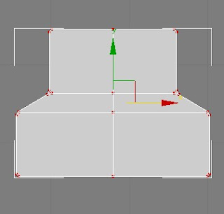

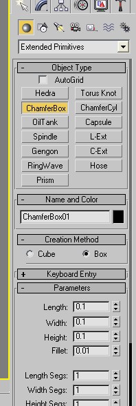
Select button Geometry, in the drop-down menu select Extended Primitives, and then create a ChamferBox. Modify the parameters, set its size. Converted to editable poly, adjust point position.

Create two Cylinder, modify the size. Choose one of the Cylinder converted to editable poly, adjust point position according to the photos.

Makeing of this part, firstly, I created two boxes and then combined them, converted to editable poly, select points to modify.

When I finished all components, I assembled them together according to the photographs. This part is complete.

The remaining part is the details of the production, these details is a difficult part in the whole model. When I made this part, it spent a lot of time. Firstly, I must make out the overall shape, and then adjust the location of the point to achieve the final results. This part is inside of the component, the photographs were not very clear, so in some places I must guess it to create, through the Internet I saw the internal structure of component, and then I made out the model according my own ideas. The method is very simple, in some places are very similar. The internal parts as the picture show. This part of the part is mainly to create ChamferBox, box, Cylinder, Sphere, adjust the location of points and the parameters. This part is similar with the previous part of the production.

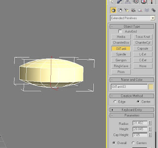
The next step is the production of several small components. The method of produced screw is the used of Boolean operations. As the picture show, When the production of the parts, I created an oiltank. Then go to modify panel to change parameters and improving the number of segments, transformed into editable poly adjust point position. And then create two boxes, it will be placed cross.  >
>  > Compound objects> Boolean, select a copy mode, and then click the
 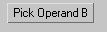 pick up box, and then adjust the control panel in the parameter calculations. Access to modify panel to modified. Then copy a screw.
 >
>  > Compound objects> Boolean, select a copy mode, and then click the
  pick up box, and then adjust the control panel in the parameter calculations. Access to modify panel to modified. Then copy a screw.

create a Tube, edge into 6, converted to editable poly, adjustment points. Using the same way, create a Cylinder. The model was modified shape according the photo.


Create tubes
First, I created a Cylinder, modify the parameter
 converted to editable poly, select point, through the select and rotate, select and move, select and uniform scale, and adjust the tube position. And then create a 3 Cylinder, making the top of the tube, methods and the same as before. The effect is shown in picture.


The remaining small parts production Method is similar with before methods. The final work is assembly component according with photos. The final results as shown. 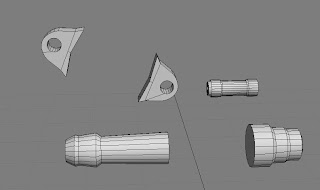

The production of the whole model is not difficult, but needs careful, because there are many details of the component. The entire production process, I have some trouble, through reading books, watching tutorials, ask my classmates, finally, I solved these problem.

No comments:
Post a Comment