Through this group work, I learned a lot of new knowledge. Model is mainly produced separately. The most important part in the model is the details. In these parts of the components we must grasp the link of every component. It is not easy for me. When I began to get the model I am not very clear how to make it. I found some tutorials from the Internet, while reading some books which is the production of mechanical models. Through my practice, I finished the model. In the production process, I met a lot of problems because I rarely making produced the mechanical model before. When I made the Carburetor model, I separated all the components, but there are some parts I do not know what methods should be used. At the same time it is easy to make the model more precise. So I decided to use another software, this software is a specially crafted mechanical models. “SolidWorks” is a specially crafted mechanical model of the software. At the beginning I used this software, but I found some problems which I need to draw components diagram. It is an important part. If the picture is not good, the production of spare components will be more difficult. So I gave up using this software.
Finally, I decided to use 3DS MAX software to do this model. I spent a lot of time, but I found that I can use the components which are completed before to make a new components. This is saved a lot of time. Through the production of Carburetor, I learned some new knowledge. When I made another model “Lawnmower”, I feel easier. At the same time, the production of methods is similar with Carburetor. When I finished the model, the modification is very important in this work. A good model is rely on modify rather than made out. So I spent a lot of time in this part. In general, the effect of the final model is still good.
When we do the animation, I have been listened the views of groups members carefully and seriously, look at how to do this animation. Because animation is not my strong point, so I have a lot of knowledge to consult our group members. When our group members do the animation, I always observed their methods and then research it after class. So I learned lots of technologies. This is the greatest benefit in this group work. Overall, this group work is great helpful to me. I have learned lots of new technology and knowledge.
Wednesday, 9 December 2009
Animation (week10-11)
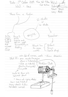
After group meetings, we identified how to create animation. When we have watched the works of Robert, we think that he has some experience of the animation so this part is completed for Robert. First, we found a video of 2 stroke engine works onto the Internet. When the group members have watched video and understand the 2 stroke engine work principle. Then we began to prepare animation. We divided our animation into 3 parts: part one was the introduction, part two was the actual demonstration of the engine, and part three was the ending of the animation. We choose the PAL (24fm/s).And then Robert had positioned the lighting and the camera he produced this opening shot. We made the first part of animation is Introduction of the engine model. In this part of the animation we need to find a good position of camera, through a series of debugging, finally we completed this part of the animation. The following video shows is that the first part of our animation.The second part is the hardest and most important part in the animation. In order to do this part we have spent some time. When the production process, our group members found some problems. The first thought was to animate the piston. The only problem was that the piston shaft did not match the cam. Robert and Mike have watched animation many times, but still have not found the problem. The other members do not understand this problem. Finally,Mike found out the problem was with the key frames so they were out of place. The next stage was to do the top of the piston animation and to start animating the flow of liquids and gases within the engine. Robert decided to use ‘planes’ with textures. The following video show is that the second part of our animation. The last part of the animation is to create scenes animation. This part is needs of the Lawnmower models which I made it and the Kiel making a scene. This is the last part of the animation. It looked more vivid, and then used audio files which made in Mike. We will complete the animation.
Sunday, 6 December 2009
Create Lawnmower
To do the method of Lawnmower is similar Carburetor. First, I divided the Lawnmower I into several parts and separately to produce each a part, finally I assembled components together. At the beginning, when I got this picture of the Lawnmower, there is a lot of places that I can not understand how to do it. The photo is got from the Internet, so the picture is not very clear. I discussed the group members. Finally, I decided to start with the simplest place of the Lawnmower. As the experience of making Carburetor, it avoided many errors in the Carburetor model.
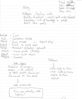
First I made the bottom of the components. Create a cone, set its parameters, and then converted to editable poly, select the vertexes and consistent with the photo to adjust the point position. Then I added a surface modification to change the model smooth. Finally, create a cone, so the bottom of the model was finished.


The production of wheels
when I made the wheels, I think my approach is relatively cumbersome, I have been looking for a good production methods, but it has not success. So I can only use this method. Despite spending a lot of time to complete these components, but the results was pretty good. First, create a Torus, and then converted to editable poly, select points, to modify. There is the more trouble in the editing process. The photograph of the wheel texture is not very clear, so I found a wheel picture from the Internet. According to photographs I made the model is becoming much easier. This method is required patience, it spent a lot of time to adjust the location of vertexes, but the result is very good. The method of connect the wheel’s components is similar with Carburetor. Create Cylinder and modify the model to reach the final effects.
when I made the wheels, I think my approach is relatively cumbersome, I have been looking for a good production methods, but it has not success. So I can only use this method. Despite spending a lot of time to complete these components, but the results was pretty good. First, create a Torus, and then converted to editable poly, select points, to modify. There is the more trouble in the editing process. The photograph of the wheel texture is not very clear, so I found a wheel picture from the Internet. According to photographs I made the model is becoming much easier. This method is required patience, it spent a lot of time to adjust the location of vertexes, but the result is very good. The method of connect the wheel’s components is similar with Carburetor. Create Cylinder and modify the model to reach the final effects.

Create Handrails
The model is mainly divided into several parts, first make a few basic models, and then adjust points to reach the final effects, finally make the model become smooth.
The model is mainly divided into several parts, first make a few basic models, and then adjust points to reach the final effects, finally make the model become smooth.

The final step is making some small components. When it finished the model, the modification is very important. In a separate production of the components, there are some parts are not match with the photo. It must be through the adjustment to be completed. First I added a Meshsmooth modifier to become smooth of the model. Then Observation, which areas is still not match with the photo. Then quit the Meshsmooth to adjust point position. Through repeated conditioning, the final match to meet the basic and photos. The same method, adjust the various parts of models. When I completed of model, I sent the model for my group members, finally we decided to put 2 stroke engine models on the Lawnmower, and then make another part of the animation.


Monday, 30 November 2009
Group meeting 4 and 5(week 9)
The meeting is focus on assembly model. When the assembly, we found some problems, every model dimensions is different and some models need to modify.
The second meeting we decided to make a lawnmower model .Finally, we will put the 2 stroke engine on the lawnmower model, and then continue to do our animation. I am responsible for do the lawnmower model. On the other hand, other group members began to record voices and make the model map, simple animation. Next week the group will focus on animating the Piston, animating the fluid movement within the engine.
The second meeting we decided to make a lawnmower model .Finally, we will put the 2 stroke engine on the lawnmower model, and then continue to do our animation. I am responsible for do the lawnmower model. On the other hand, other group members began to record voices and make the model map, simple animation. Next week the group will focus on animating the Piston, animating the fluid movement within the engine.


Create Carbureto(week 8)
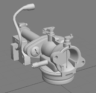
When I made of Carburetor, I decided to create biggest to smallest. First,I do each part separately, and finally make them together. I created three Cylinders, converted to editable poly, adjust the size of three Cylinders, and then add a modifier is Meshsmooth.
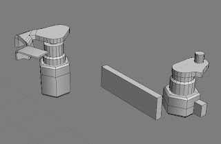
I repeat do this part a lot of times because I hope to find a suitable way to make this a part .By the end, I decided to use the Lathe process to make this part. First, I observed of photos, used the line to drawn the cross-section diagram of this part. Then add a modifier is the Lathe, modify the parameters, raise segments and press Mix button. Then it was converted to editable poly, select the vertex to adjust, remove the Cap, finally, and add a modifier is the Meshsmooth. Now, this section is complete. In the production of this part, there are some problems. When I draw the cross-section, I always do not know how to paint it. I repeated many times. Finally I got good results.


Create tubes
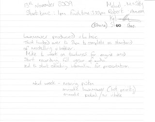
First, I created a Cylinder, modify the parameter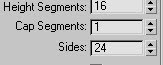 converted to editable poly, select point, through the select and rotate, select and move, select and uniform scale, and adjust the tube position. And then create a 3 Cylinder, making the top of the tube, methods and the same as before. The effect is shown in picture.


I repeat do this part a lot of times because I hope to find a suitable way to make this a part .By the end, I decided to use the Lathe process to make this part. First, I observed of photos, used the line to drawn the cross-section diagram of this part. Then add a modifier is the Lathe, modify the parameters, raise segments and press Mix button. Then it was converted to editable poly, select the vertex to adjust, remove the Cap, finally, and add a modifier is the Meshsmooth. Now, this section is complete. In the production of this part, there are some problems. When I draw the cross-section, I always do not know how to paint it. I repeated many times. Finally I got good results.

This part is similar with the previous part of the production, but it takes time to adjust vertex. In the production of this part, I import photos into 3D MAX. I use it as a reference map, in order to change the shape of component. First, create a Cylinder, converted to editable poly, select vertex. And then I adjust the point of Cylinder to similar with photos. Finally, I add a modifier is the Meshsmooth. Select the entire component, press shift button to copy. This section is complete.

This section is formed by the box and Cylinder. First, create a Cylinder, adjust the size. And then create six boxes, adjust position according to photographs, and then converted to editable poly, adjust location of the point. At the same time combined these six boxes. 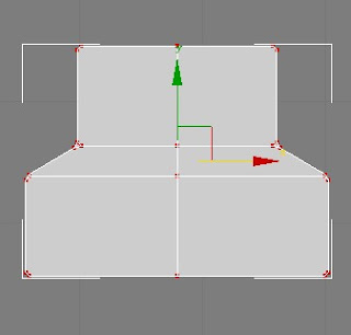

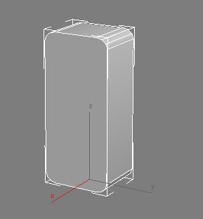
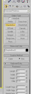
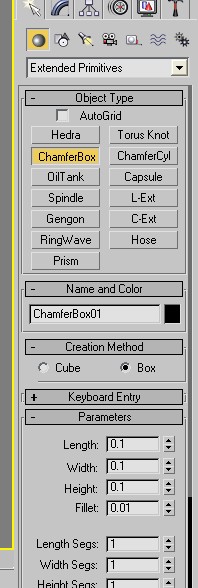
Select button Geometry, in the drop-down menu select Extended Primitives, and then create a ChamferBox. Modify the parameters, set its size. Converted to editable poly, adjust point position.

Create two Cylinder, modify the size. Choose one of the Cylinder converted to editable poly, adjust point position according to the photos.

Makeing of this part, firstly, I created two boxes and then combined them, converted to editable poly, select points to modify.

When I finished all components, I assembled them together according to the photographs. This part is complete.

The remaining part is the details of the production, these details is a difficult part in the whole model. When I made this part, it spent a lot of time. Firstly, I must make out the overall shape, and then adjust the location of the point to achieve the final results. This part is inside of the component, the photographs were not very clear, so in some places I must guess it to create, through the Internet I saw the internal structure of component, and then I made out the model according my own ideas. The method is very simple, in some places are very similar. The internal parts as the picture show. This part of the part is mainly to create ChamferBox, box, Cylinder, Sphere, adjust the location of points and the parameters. This part is similar with the previous part of the production.

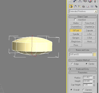
The next step is the production of several small components. The method of produced screw is the used of Boolean operations. As the picture show, When the production of the parts, I created an oiltank. Then go to modify panel to change parameters and improving the number of segments, transformed into editable poly adjust point position. And then create two boxes, it will be placed cross.  >
>  > Compound objects> Boolean, select a copy mode, and then click the
 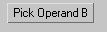 pick up box, and then adjust the control panel in the parameter calculations. Access to modify panel to modified. Then copy a screw.
 >
>  > Compound objects> Boolean, select a copy mode, and then click the
  pick up box, and then adjust the control panel in the parameter calculations. Access to modify panel to modified. Then copy a screw.

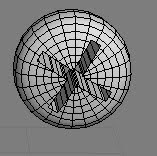
create a Tube, edge into 6, converted to editable poly, adjustment points. Using the same way, create a Cylinder. The model was modified shape according the photo.


Create tubes
First, I created a Cylinder, modify the parameter
 converted to editable poly, select point, through the select and rotate, select and move, select and uniform scale, and adjust the tube position. And then create a 3 Cylinder, making the top of the tube, methods and the same as before. The effect is shown in picture.


The remaining small parts production Method is similar with before methods. The final work is assembly component according with photos. The final results as shown. 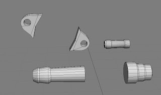

The production of the whole model is not difficult, but needs careful, because there are many details of the component. The entire production process, I have some trouble, through reading books, watching tutorials, ask my classmates, finally, I solved these problem.

Sunday, 29 November 2009
Preparation (week 7)
In this week our group started to do model. This can improve work efficiency in a short time. My task is to produce Carburetor. Initially I do not understand how to make this part of the Carburetor. I have read a few books and go onto the Internet to find some tutorials to learn how to make this section. Our group members gave me some photos about this engine. I have studied each part of the structure and try to understand how to make this part. It is in order to prepare for production of Carburetor.


Group meeting3(week 6)
Through the group meetings, I understand that our team needs to be done in this work. Firstly, we decided to do the model, we need one week to complete the production of machine model. Secondly, we can assembly Model. During the discussion, we found that the hardest part is the animation; we need not only understand the whole process of the machine movement, but also need to consider how to create animation. It is need to consider the issue with each group members. Therefore, we focus on how to do the animation. For the 2 stroke engine I do not understand how it works. In order to do the work I looked some information about 2 stroke engine working principle on the internet. While our group members used their knowledge to explain 2 stroke engine working process for me, which makes me understanding of machinery. After group discuss, we believe that the whole explain of animation is very important, because each machine works are different. Therefore, in video, we need to tell the audience the works of machinery. When the viewers watched video, they can understand of the engine work process. This is the outcome of the discussions in our group at the beginning of production.


Thursday, 22 October 2009
Summary
Through this five weeks study and production, I learned a lot of things. First through the tutorial to explain, I know that how to build the 3D head model. Through my own practice I found some problems in the production process. First of all, during the look at the tutorial, my biggest obstacle is language because in some places I did not really understand what it means, and then I repeated viewing and my own practice. Eventually overcome this problem. I have not enough experience, so there are some problems in the production process. Such as when I drawing the wiring diagram I did not grasp the character's facial features, so leading to a final model have some mistake, but the result through my own observations and the revised to solve this problem. On the other hand there are also some technical problems. When I make the UV mapping, there is an error which leading to the location of the map was wrong, but later I watching tutorials again and research it by myself. Eventually I used a different approach to do the UV mapping and put the map to the appropriate location. In short, in this production process, I not only learned a method from the tutorial, but also developed another method.
Although the final works were not achieved the desired effect, but it is still to complete this work. If I had more time to learn production techniques, and accumulated enough experience, I believe I will do it better.
Although the final works were not achieved the desired effect, but it is still to complete this work. If I had more time to learn production techniques, and accumulated enough experience, I believe I will do it better.
Wednesday, 21 October 2009
creat hair
First, adding a hair and fur modifier, select polygon button, select the required implantation of the hair area. The next is to modify the parameters of hair count, hair segments, hair passes, material parameters, change hair color. The next step is the design for the head hair. First select the style hair button into the hair design editor to make the hair to the head model. Next, select the shake mode button, let the hair to change natural droop, then select the button of puff roots, and change the hair roots to become fluffy. After that use of bush mode, translate to adjust the shape of the hair. In this production process, I encountered some problems, such as the shape of hair can not be adjusted to a suitable location. Another one is I spent lots of time to do the hair materials because I can not find particularly suitable of the material. Ultimately, through adjust the high-light and gloss to deal with hair texture.
Statement: create hair I was using the 3DS MAX 8.0, this version provides a hair and fur system. Head model I was using the 3DS MAX 9.0 software to build it.


Statement: create hair I was using the 3DS MAX 8.0, this version provides a hair and fur system. Head model I was using the 3DS MAX 9.0 software to build it.


Tuesday, 20 October 2009
group meeting notes
Our group meeting mainly to discuss our final work to be done .We agreed that an engine would be the most practical exhibit to create. We decided to go for the 2 stroke.
Once created the group would then have to look into produce:
- Textures
- Lighting
- Camera work
- Animation
On 23th oct ,we will continue to discuss the work of each member needs to be done, and the production process.
Once created the group would then have to look into produce:
- Textures
- Lighting
- Camera work
- Animation
On 23th oct ,we will continue to discuss the work of each member needs to be done, and the production process.
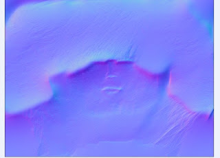
uvw mapping
Firstly, the model must first expand UV, and then go to the photoshop to use photos on the UV map, and then posted back to the model. During the whole operation will be a lot of problems, first of all expand UV, this is the most important part in this process. It relates to the mapping can paste in the right place, so each part must be careful. I followed tutorials again and again, but I was having problems with the mapping. So I have done it again and again finally I found the problem. After the exhibition in the UV map, we should relax the map, this operation has been designed in 3D max
, but some points still get together, so I need to put each point to the appropriate place. The next step is to export the UV map out of the 3D max software, converted to. tif format files into the photoshop software for mapping. This is a very complex task. First, I looked several times repeated tutorials and found a few more crucial part. Then I began to make the map. In the process because of his lack of experience, the UV map is a flat, while the photos are different from it. So I always can not find the exact location. But through the constant adjustment, get the final result.
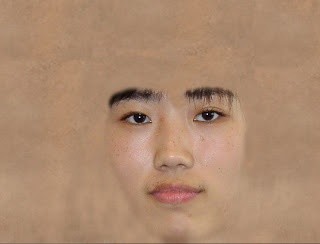
, but some points still get together, so I need to put each point to the appropriate place. The next step is to export the UV map out of the 3D max software, converted to. tif format files into the photoshop software for mapping. This is a very complex task. First, I looked several times repeated tutorials and found a few more crucial part. Then I began to make the map. In the process because of his lack of experience, the UV map is a flat, while the photos are different from it. So I always can not find the exact location. But through the constant adjustment, get the final result.
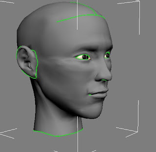
creating a nose,mouth,ear and back of the head
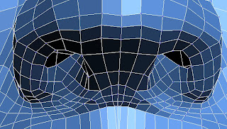
Creating nose
This part is difficult for me, because I spent quite a long time to learn how to do it by video, I used copying edges, and extrude method to finish it. Through the video I finished it.
Create mouth
Part of the mouth and nose are the same, and also by copying edges, adjust points. The process was very simple, and basically the same as when construction of the nostrils, selecting each of the edges, and then clicking and dragging with the scale tool, while holding down shift. Go to the front view to adjust point.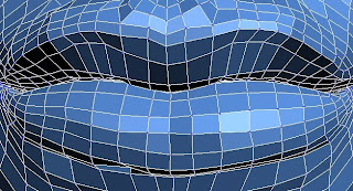
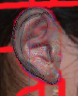
Create ear
I followed the video to learn to do ear model, but in the end I did not finish it. The problem I found is that I started concentrating too much on what the ear in the tutorial looks like. And some areas I do not quite understand what to do. Then I changed methods. First, the establishment of a rectangular box, converted to poly. Then I add a curve in the space. This curve should conform to the ear shape, and then continue to edit, at the modify command of modify, click the create shape from selection button and then select the pick line, at just pick up the curve, with the extrude command, and then adjust the location of points. Then I used cut command to add the lines, continue to adjust the location of points. Finally add a Mesh smooth command.
create back of the head
Create a sphere ,this sphere has to be of the same size to the face. Using the scale tool, I scaled the sphere to make it round the head shaped. After this, I changed the rectangular selection tool to paint selection. and then, holding down the ctrl key, choose not to be used place, and then delete. The next step was to delete the right side of the sphere and then to adjust points. The next step is mirror, the separation point welded together. And then continued to made neck. Through the copy the edge and regulation of points. Production method is similar with method of made the mouth. When I begin to make back of the head and neck, the problem is how to make a smooth surface. I choose to cut lines and then adjust point. Ultimately achieve the desired results.


Thursday, 8 October 2009
3D face
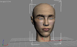
This week I continue made my 3D face.
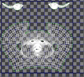
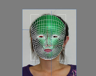
The main task of this week is to create the character's face model. Firstly, in the 3D MAX, Select front view, create lines, according a good wiring diagram of the picture painted to create lines. After it, select one of the closed frame into editable poly and then select the attach all of the lines add together. To welded to the separation of vertex. But in the welding process, some points are not welded, so I chose to use target welding method to weld point.This process must be avoided the triangle in order to facilitate the adjustment point position. Then go to the left view, based on the facial structure of the photo will adjust to the right position. This process is the very important and spent lots of time but also some areas in need of careful. I must carefully adjust the location of every point. Turning to perspective, and then continue to adjust each point.
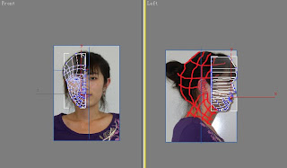
The next step is to complete the face model to make it. It can be achieved in two ways, one is a mirror, and another is to add a Symmetry Modifier. At first I use the mirror, but when the mirror finished, there are some problems that I discovered there are some points not in conformity with the location of photos and some points can not be welded together, so the ultimate effect of this method can not be achieved, I chose another method to add a Symmetry Modifier. The benefits of this method is that if I found something was wrong I can delete and re-do at the same time, this method can also be easily adjusted to point to the appropriate location of the photo.
Subscribe to:
Comments (Atom)